CWT Compact S2 Installation & Maintenance Manual
| Note: For earlier versions of the CPU board see earlier issues of this document |
The CPU board consists of a main printed circuit board assembly. It contains a 32-bit 800 MHz processor with a 256 MB non-volatile flash memory used to store the operating system (Windows CE) and a 512 MB RAM. The latter, including the real-time clock, is backed up by a battery positioned on the CPU board.
| Important: This board requires Compact AVR AVE version 3.0.0.28 or later |
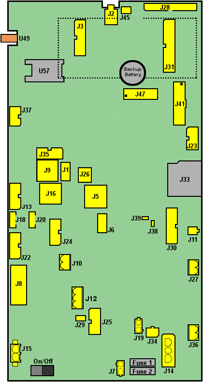
The figure below shows the positions of connectors etc. The figure is followed by a list of all connectors and their use.

Figure 26, CPU board version 0501-E0150 Rev H
Connector |
Com port |
Type/Outlet name |
Function |
|---|---|---|---|
F1 |
|
|
4A Fuse ATO |
F2 |
|
|
10A Fuse ATO |
J1 |
|
USB0A |
USB 2.0 Host Type A |
J2 |
|
|
Speaker |
J3 |
|
|
Expansion board |
J4 |
|
|
Not mounted |
J5 |
|
|
Ethernet |
J6 |
|
USB1 |
USB 2.0 host type A |
J7 |
|
12Vprinter |
12V Printer from Battery |
J8 |
Com 7 |
External SPI UART |
Serial 2 |
J9 |
Com 2 |
|
CWT Cap Bus |
J10 |
|
IN#1 |
Opto coupled input. E.g. Seismic alarm |
J11 |
|
Zl-Air Battery |
Extra battery Zink-Air |
J12 |
|
RELAY |
Relay Output |
J13 |
Com 9 |
Internal iMX53 UART |
Serial 4 (5V_COM_9) |
J14 |
|
Bat. IN |
Battery 12 V In |
J15 |
|
24Vprinter |
24V Printer |
J16 |
|
CWT-CAP BUS |
CWT Cap Bus |
J17 |
|
|
Not mounted |
J18 |
|
Coin-Box |
Coin Box pin 1 and 2 Lower Door pin 3 and 4 |
J19 |
|
|
12 V to External Pay Unit (12V_1) |
J20 |
|
Door-SW |
Upper Door switches |
J21 |
|
|
Not mounted |
J22 |
Com 8 |
External SPI UART |
Printer - Serial 3 (5V_COM_8) |
J23 |
|
Status LEDs & Ambient light |
Status LEDS and Ambient light sensor |
J24 |
Com 1 |
External SPI UART |
Touch controller - Serial 5 (5V_COM_1) |
J25 |
|
|
AVR JTAG for loading of AVR software |
J26 |
|
USB0B |
USB Device type B |
J27 |
|
SolarPanel36cell |
Solar Panel 36 cells Input |
J28 |
|
STN-LCD |
STN Display |
J29 |
|
|
12 V Out from Battery (12V_2) |
J30 |
|
debug |
Debug port |
J31 |
Com 4 (** |
Internal iMX53 UART |
Expansion board (5V_COM_4) |
J32 |
|
|
Wake up button |
J33 |
|
|
SD Card |
J34 |
|
|
External Light |
J35 |
Com 3 (* |
Internal iMX53 UART |
External pay unit or bill reader - Serial 1 (5V_COM_3) |
J36 |
|
SolaPanel |
Solar Panel |
J37 |
Com 3 (* |
Internal iMX53 UART |
External pay unit or bill reader - MDB (12V_MDB) |
J38 |
|
Boot Mode |
Boot Mode |
J39 |
|
Fuse Volt |
Fuse Voltage |
J40 |
|
|
Not mounted |
J41 |
|
Colour Display |
Colour display with LDVS and Backlight |
J42 |
|
|
12 V Printer |
J44 |
|
|
Not mounted |
J45 |
|
|
Microphone |
J47 |
|
|
JTAG imx53 |
J48 |
|
|
Not mounted |
J49 |
|
|
Not mounted |
SW8 |
|
OFF ON |
On/Off Switch |
U49 |
|
WGSM |
Modem Antenna |
U57 |
|
|
SIM Card |
