CWT Compact S2 Installation & Maintenance Manual
The CWT Compact terminals also have an optional electronic lock system with online central administration and authorization via WebOffice. This solution replaces the expensive and tedious handling and administration of keys because all persons that need access to a CWT Compact use the same type and version of door key that is more to be seen as a door opening tool.

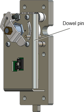
Figure 20, Electronic-locking mechanism.

Figure 21, Door key for electronic locks
There is a round key hole at the right side of both the cabinet and the pedestal.
The inside of each hole is covered by a protective plate. To enable the insertion of a key, this plate will automatically move out of way if these conditions are met:
•You are registered as a user in WebOffice and have been given the proper privileges for access times, opening frequencies, compartment (cabinet, pedestal or both), etc.
•You identify yourself by inserting an access card in the card reader and entering an optional PIN code at the keyboard (CWTC S3A with keyboard and CWTC Touch). In a CWTC S3A without keyboard and in terminals without a card reader, you place a special ID card against an RFID reader mounted in the plastic casing in the right bottom corner.
| NOTE: After you have opened the upper door, the lock will be closed again after a 15 second time out to save power. Because the terminal now is in the service mode you cannot prove your identity and get the necessary privilege to open the door again. Instead you have to press an Open Upper Door key shown in the start page of the service menu to open the lock mechanism again. The pedestal door lock also has a 15 second time out, but you can still run the normal application with the upper door closed and open the lower door lock as usual. |
Master key
The electronic lock system also provides an opening alternative in case of power failure, software failure or communication disturbances. Inside the electronic lock there is a regular lock as well. A mechanical master key is used for emergency access, but the protective plate has to be pushed up manually first by means of a small screwdriver, paper clip, or similar.
Latches
The electronic lock has a relay operated latch mechanism that prevents anyone from opening the key lock unless the person can prove his identity.
| Note: The minimum voltage required for proper operation of the electronic locks is 11.1 V at room temperature (20 ˚C). |
Configuration of the E-locks
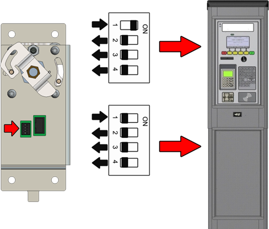
The upper and the lower E-locks are of the same type. Each lock is a DIP-switch whose setting tells the system if the lock is mounted in the cabinet or pedestal.
The E-locks are connected to the CPU board (Connector J16) board
Please note that if an upgrade from mechanical to electronic lock is desired, the locking bar also needs to be replaced.

Figure 22, E-lock DIP switch settings
