CWT Compact S2 Installation & Maintenance Manual
A PCB assembly named Coin Handling Board is mounted on the left side of the coin unit.

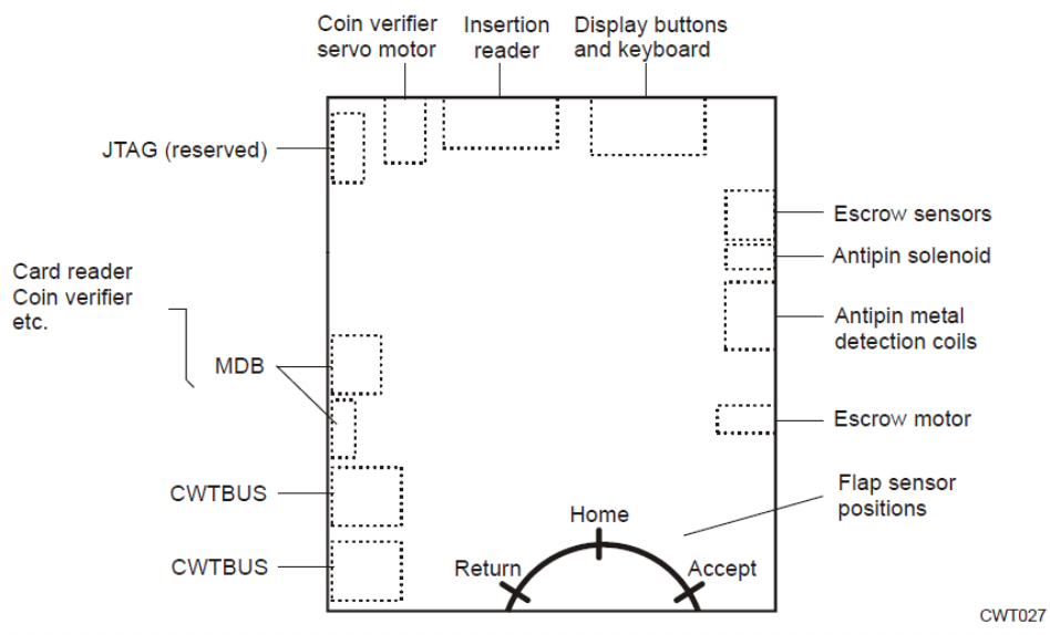
Figure 11, Coin handling board as seen from the solder side.
The coin handling board, with its own AVR (micro controller), controls the functions of the coin system module. The board, which connects to the CPU board via the CWT BUS, also serves as an interface between the display buttons in CWT Compact and an optional card reader. The AVR firmware can be updated using a PC.
A screen print at the bottom of the board indicates the position of the flap sensors mounted on the component side. The sensors are affected by the tiny permanent magnet fitted on the flap pulley.
