CWT Compact S2 Installation & Maintenance Manual
Removal
1.Disconnect the cables from the E-lock.
2.Remove four nuts and remove the E-lock. A small box spanner (10 mm) is required to remove the lower E-lock due to limited space.
Assembly
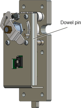
Ensure that the dowel pin (see arrow) mates with the locking latches.

Figure 44, The dowel pin should mate with the locking latches
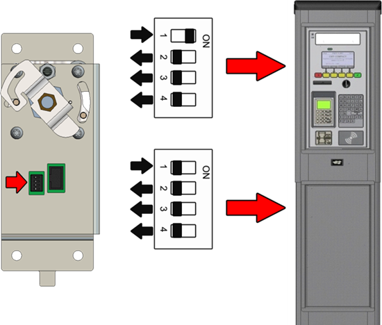
Check that the DIP switch setting corresponds to the E-lock position in the terminal.

Figure 45, E-lock DIP switch settings
Start the terminal and close the cabinet door to get a printout showing the version of the E-lock AVR program. If necessary, update. See more about AVR updates in the CWT Software Configuration Manual.
